This is an old revision of the document!
Hysteresis Loop - The RPC Control Box
Overview
Here we have the box containing the RPC modules that control the hysteresis loop demonstration.
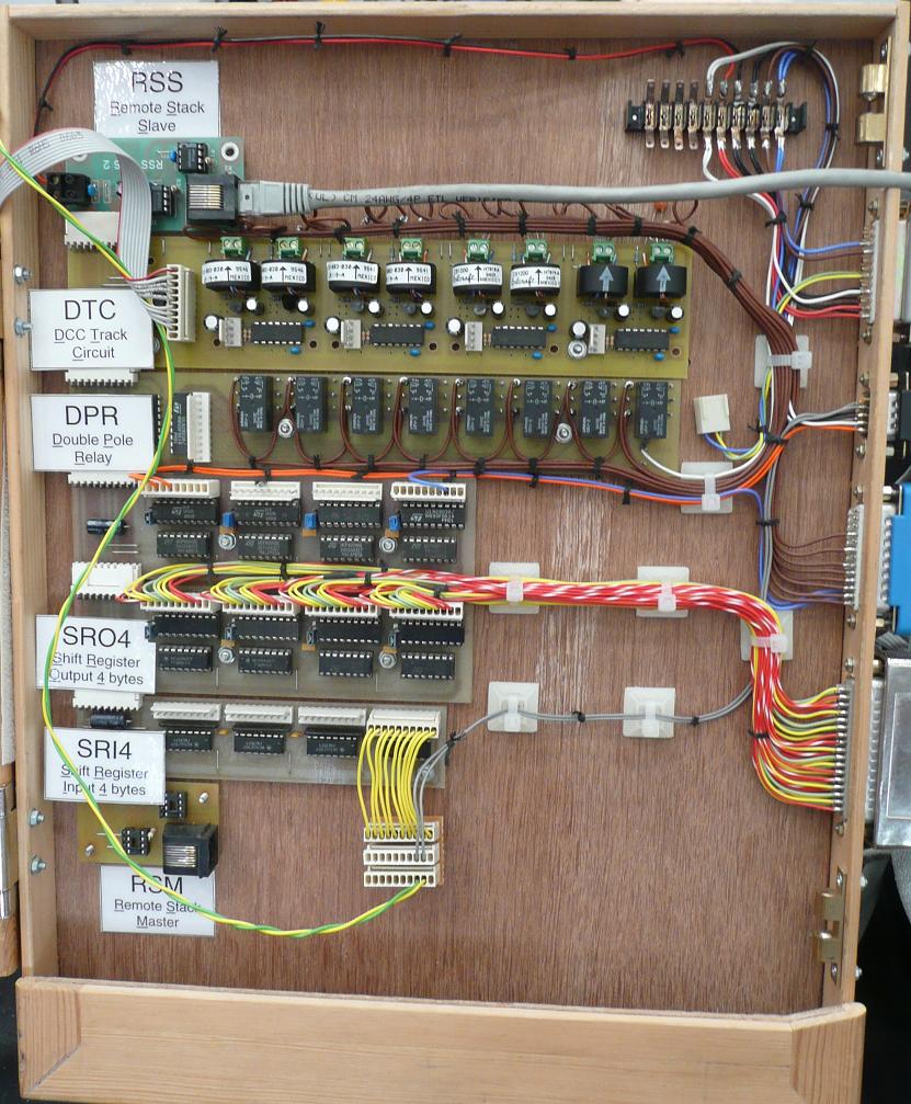 At the top, connected to a grey Cat5 cable coming in from the right is a RSS (Remote Stack Slave), moving down the 'Stack' we have next a DTC (DCC Track Circuit) this provides the track occupation feedback. This module replaces the original FTC (Floating Track Circuit) used previously, the loose connector provided the 'Bias voltages' required. Next there is a DPR (Double Pole Relay) module, the demo was originally designed for DC operation and this board controls power feed to the track, in DCC mode all relays are switched on so power is fed to all track sections. Next there are two SRO4 (Shift Register Output x 4 bytes) modules, the first is very sparsely populated, the two orange wires control the point motor drivers and the blue one controls the 'feather' on the first signal. The second SRO4 is fully populated and these wires go to the 8 four aspect signals. The last module used in this configuration is the SRI4 (Shift Register Input x 4 byte) module, this again is sparsely populated, having just two grey wires from the switches mounted on the point motors, these provide the point position feedback. The connector with the grey wires would normally be connected directly to the module, the breakout arrangement here was to allow the point position to be fed to a separate demonstration, as was the ribbon cable connected to the DTC. Lastly on this stack is a RSM (Remote Stack Master), not used here.