Model Electronic Railway Group
The Leading Society for Model Railway Electronics
Diode Matrix Interlocking
A suggestion from Colin Glenister (26/2/2000)
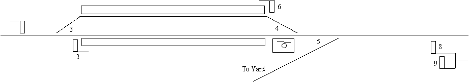
Single Track Station with Passing Loop & Yard
Locking Table
| Lever | Locks | Releases | 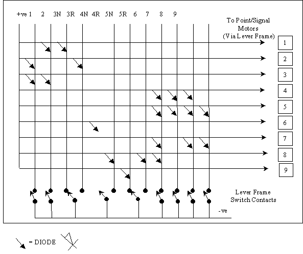 |
| 1 | 2, 3 | ||
| 2 | 1, 3 | ||
| 3Normal | 1 | 2 | |
| 3Reversed | 2 | 1 | |
| 4Normal | 6 | 2, 8 | |
| 4Reversed | 8 | 6 | |
| 5Normal | 9 | 8 | |
| 5Reversed | 8 | 9 | |
| 6 | 4, 5, 8, 9 | ||
| 7 | 4, 5 | ||
| 8 | 4, 5, 7 | ||
| 9 | 5, 7 |
Matrix Operation
The matrix comprises a number of unconnected horizontal & vertical electrical ‘lines’.
The vertical lines carry the matrix inputs or interlocking signals from point motor/signal relay contacts. In this example the common terminal of these contacts is connected to, and switch, the (-ve) terminal or circuit earth.
The horizontal lines are the matrix outputs to the point motor or signal relay coils. One end of all these lines is connected to the (+ve) terminal of the power supply; the other end of each line is connected to the coil of a point motor or signal relay.
Connections between the input and output lines of the matrix are made via diodes such that the (+ve) supply to a locked point or signal is fed through a diode and a closed point or signal contact to the (-ve) terminal. In practice each of these input lines would carry a lamp or LED to act prevent the (+ve) and (-ve) terminals of the power supply being shorted together.
A Simple Example
Let's Signal 1 and Point 3.
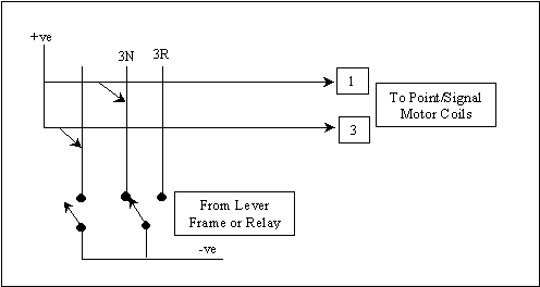
Operation
- Signal 1 controls entry to upper platform only.
- Point 3 locks Signal 1 on when Normal
- Point 3 releases Signal 1 when Reversed
- Signal 1 locks Point 3 when Off
In current state:
Contact on Signal 1 open therefore Point 3 is released:
(+ve) voltage travels along output line to Point 3 motor coil (No connection to (-ve) through diode A and contact)
Point 3 is Normal therefore Signal 1 is locked On:
(+ve) voltage is prevented from reaching Signal 1 relay coil as it is rerouted to (-ve) terminal via the diode B and the closed change-over contact on Point 3.
Route to Platform Set
Point 3 Reversed:
Change-over contact on Point 3 opens 3N line and connects 3R line to (-ve)
Signal 1 is released: (+ve) voltage now flows along output line to Signal 1 relay coil
Signal 1 pulled Off:
Contact on Signal 1 is closed and connects Signal 1 line to (-ve)
Point 3 is locked: (+ve) voltage now flows to (-ve) terminal via diode A and closed Signal 1 contact.
Refinements
- Add lamp or LED to input lines above the contacts to show the state/position of the Signal or Point.
- Add an extra, switched, (+ve) feed to all Point/Signal coils for interlocking override.
- Incorporate Single Line Staff by adding an input and output line for each staff
- Add level crossing interlocks