Model Electronic Railway Group
The Leading Society for Model Railway Electronics
MERG Shuttle Controller System (ATC).
Revised: 5th December 2020. Kit design and original text: Gordon Hopkins.
Introduction
The Shuttle system design presented here has evolved over several iterations to emerge as a very capable and adaptable system, which can be expanded at will by the addition of extra switching circuits, external to the main shuttle controller module.
The aim has been to provide as much flexibility as is reasonably possible, with basic shuttle style functionality built-in, but with many options for additions or expansion in various ways for the more adventurous.
The acronym ‘ATC’ is intended to denote ‘Automatic Train Controller’ because the design could have many uses other than just as a shuttle system.
Fundamentals
The ATC shuttle control module is intended for analogue DC track operation only. It includes control over acceleration and braking rates to provide smooth operation. The module is not suitable for DCC.
The shuttle module is intended for controlling the movement of one item of motive power. This does not mean that only one train can be used with the system, merely that only one can be in motion at a time. Simultaneous motion would require the use of multiple shuttle modules, interconnected to form a co-ordinated system.
A simple form of multiple operation is already incorporated, known as ‘shuffle’ mode, where adjacent identical modules inform their neighbours whether their track section is clear or not, which allows a simple ‘elephant parade’ arrangement to be implemented. Ideal for tram systems where one tram follows another along the same track, or for hidden yards where several trains are stored on each track. ‘Shuffle’ mode requires the use of one ATC module per section, with adjacent modules connected together to cascade track occupation information between sections to avoid collisions.
A pre-programmed PIC microcontroller controls all aspects of the ATC module operation. The PIC program implements fixed sequence operations whereby train movements follow set patterns defined in the form of look-up tables stored in the PIC memory. These tables can be added to, or modified at will to implement almost any movement sequence the user can devise.
Operationally, as each train movement completes, the next set of sequence information is read from the table and the section controls set up accordingly, ready for the next train movement. The selected sequence is repeated continuously until switched off.
It is anticipated that for the majority of users, the set of five pre-programmed sequences for the most common track configurations will suffice. However, bespoke versions are quite straightforward to implement, and if new configurations are encountered solutions can be created and loaded into the module using the Bootloader Interface (ABI module).
Power to the track is derived using a standard variable voltage regulator arrangement, with speed variation implemented by the PIC using Pulse Width Modulation (PWM).
Fundamentals - contd....
Five variable or ‘Parameter’ controls are provided.
First is the control which sets the track voltage. This control has no connection to the PIC as such, simply being part of the variable regulator circuit. It effectively sets the maximum speed when the PWM is at 100% duty cycle, i.e. fully ‘ON’.
The remaining four manual controls affect other aspects of train operation. As standard, these are ‘Acceleration’, ‘Deceleration’, ‘Dwell Time’ with the last as a ‘Spare’. These controls are read into the PIC as analogue voltages which set the rates of operation of these features. Typically, clockwise rotation of the control increases the effect of the parameter – so that more clockwise equates to longer acceleration & deceleration times and longer dwell time.
The shuttle controller is designed to be powered from a smoothed DC supply with a range of 9V to 18V, nominally 15V. The MERG kit locker can supply suitable power supply units with the kits.
All standard types of point motor can be controlled through the system by adding the appropriate MERG kit for that type of motor. For driving solenoid motors this might typically be the PD3 kit (Kit 37a or 37b). Other methods could include operation of slow-action motors using the changeover relays of a MERG Kit 74, or servo operation using the ‘Servo4’ Kit 75. Section switching is achieved using one or more external modules, known as the CSR4 (Cab Select Relay 4) as each one allows control of up to four stopping sections (or ‘ENDs'). The CSR4 module is controlled and powered by the ATC module using a connecting ‘Expansion’ cable, and several may be daisy-chained together with ‘Cascade’ cables to provide as much switching as is necessary for the intended system. A diagram detailing the connections for the Expansion and Cascade cables is included in the kit documentation.
The standard ATC module kit includes operating modes for both standalone operation and for opersation with a single additiona CSR4 kit, allowing various track configurations with up to four ‘END’s. Allowance is included in the Mode Selection for running each multi-end track configuration with any number of trains up to the maximum possible for that configuration. This permits reduced running during periods of rolling stock maintenance, for example.
Complex arrangements can be accomodated using additional CSR4 kits and or additional ATC modules for shuttle mode. More complex systems may require variable speeds and delays at different stages of the sequence, a module design is available to implement this feature but is not available as a kit.
1. ATC module, kit 45
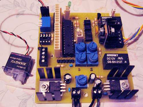
Includes provision for one servo that can be used for a signal or point if required. Using the servo for a point will need use of a CSR4 as well as you will then have configuration B.
2 CSR4 module, kit 46, Cab Select Relay 4.
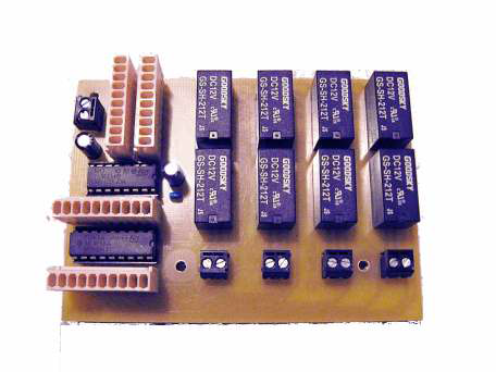
One of these needed to use any of configurations B to E. Up to 4 CSR4s can be used for more complex layouts with up to 16 stopping places. Note any layout designs other that A to E will need an ABI module as well, and a computer, to load new configurations into the ATC module.
3 ABI module, kit 47, ATC Bootloader Interface.
Used to load custom sequences for the ATC module, essential if going beyond the default confugurations A to E. The sequences are generated on a computer using an Excel spreadsheet.
Comprehensive documentation is available with Kit Instructions, Technical Bulletins and Knowledgebase articles giving full details on using the sytem.
The pre-programmed Track Configurations for shuttle operation are shown in Figures 1 to 5 inclusive.
Figure 1 - Shuttle Configuration A (Uses ATC kit standalone, one train only)

Figure 2 - Shuttle Configuration B (Uses ATC and CSR4, maximum of 2 trains)
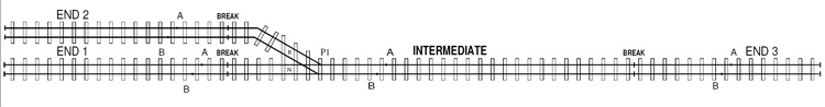
Figure 3 - Shuttle Configuration C (Uses ATC and CSR4, maximum of 3 trains)
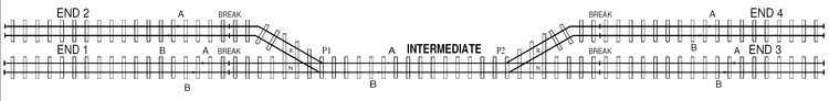
Figure 4 - Shuttle Configuration D (Uses ATC and CSR4, maximum of 3 trains)
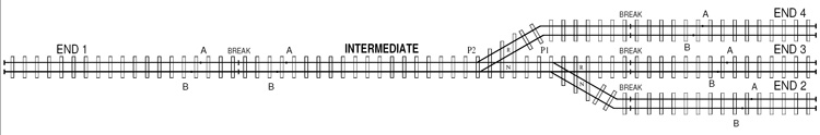
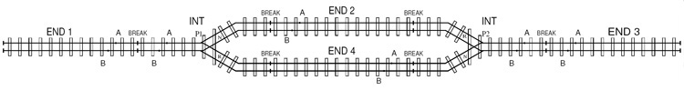
Figure 5 - Shuttle Configuration E (Uses ATC and CSR4, maximum of 3 trains)
Copyright
Copyright for items on this website is retained by the authors. Further licensing details are available on our copyright page.
The use or misuse for the sale, design, supply, process, installation, delivery, test, repair, servicing, and alteration of the designs, instructions, computer code, photographs, circuits, and any other information that appear on this web site is entirely at the risk of the user or visitor to the web site. The information is made available in good faith without warranty of any kind strictly on the basis that no liability will attach to the Model Electronic Railway Group (MERG), its officers and members.