Model Electronic Railway Group
The Leading Society for Model Railway Electronics
NMRA compatible DCC System from MERG
Revised 19th July 2023
Introduction
The MERG DCC system has been largely developed by Mike Bolton and Gil Fuchs with help from other members including Gordon Hopkins and John Eato. The system follows the NMRA DCC standards. MERG is registered with the NMRA as a manufacturer with the id #165. The original versions were designed to be easier to use than most commercial systems for those used to more conventional Model Railway controls. These designs are now over 20 years old and somewhat dated in relation to recent developments in commercial DCC such as decoders with sound etc. With the development of the MERG Layout Control Bus ie CBUS by Mike Bolton and Gil Fuchs the opportunity was taken to develop a new DCC command station and handset (CAB1, now upgraded to CAB2) with up to date features whilst using the CBUS for communication between handset and command station. (NB. CBUS is a registered trademark of Mike Bolton). This provides for simple connection to a computer if desired and for wireless operation using an IPOD touch or similar gadget as the handset. The DCC units can be used as a purely DCC system or can be integrated on a common bus with any other CBUS modules. More details of the CBUS system are on the CBUS page. Full details of the original DCC items can be obtained on the DCC Downloads page.
Kits
Kits for the command station, handsets, booster, accessory decoders, district cut outs and block occupancy detectors are available to MERG members. Members should check the Technical Bulletin and Kit pages in the members area for technical descriptions, build instructions and availability of kits. Brief descriptions of most of the current kits are given below. For various reasons we cannot supply to non-members.
DCC Command Station (CANCMD2) Kit 91A.
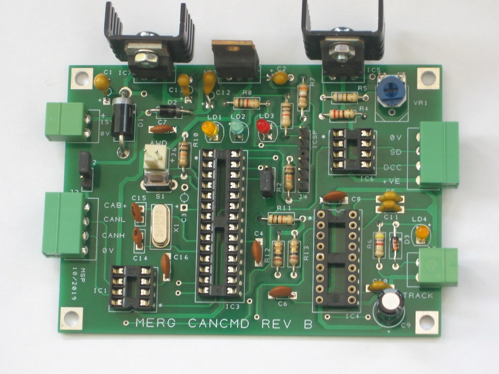
Recently revised to take a DC 15 - 18 V power supply, this is a full function command station and forms the core of the MERG DCC system. the command station includes a DCC output rated at 1 Amp that is suitable for operating a small layout or for connection to a programming track. A second output is available to connect to external boosters where a layout needs a higher current. When a booster is connected then the programming track can be used simultaneously with the layout operation. Control input is via a CBUS connection which enables control from the CANCAB handsets, from a computer connected to CBUS or from mobile phone apps linked in via a CANPiCAP kit. It is also possible to operate DCC accessories from panel switches linked into the CBUS.
DCC Control Handset (CANCAB2) Kits 92P, 92E.
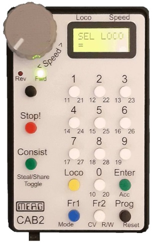
This is a handheld controller for the MERG DCC system. It has facilities for selection of 2 and 4 digit addresses and for operation of the full range of 28 functions. It can also deal with reading and writing CVs (Control Variable) to DCC decoders. The kit has been revised to remove the need for surface mount soldering and to provide a back lit display screen. The P variant has speed control by a potentiometer The E variant has speed control by an encoder which some find easier to use, especially when taking control of moving locos.
District Cutout module (DCO) Kit 57.
This is a simple cutout without auto reverse and can be used to divide a layout into districts so that a short on one district does not shut down the whole layout. This cut out is suitable for use with any NMRA DCC system rated at more than 1.5 Amps
Booster (NB2) Kit 59A
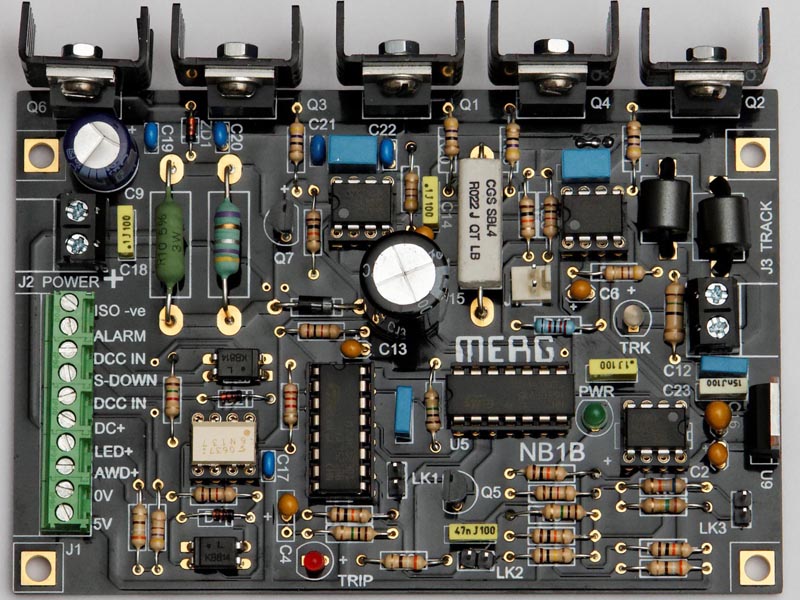
This unit provides a power booster for use where a layout needs a bigger power supply than the system unit can provide. The unit can be built for 5 or 10 Amps rating to suit your layout characteristics and needs an external DC power supply of at least 15 Volts. The booster is suitable for use with the MERG system or any commercial DCC system. Note that the picture shows the now obsolete NB1B, the NB2 is similar but reworked to avoid obsolete components.
Handset Rack Kit 673
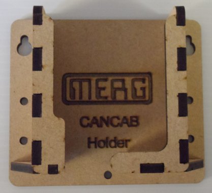
When using the MERG DCC system, it is useful to have somewhere to park any handsets not requiring immediate attention. There is a tendency for any not actually in a hand to tumble to the floor, assisted by the weight of the cable. A rack has been constructed which holds them conveniently. This is made from laser cut wood and is simply glued together and screwed to a convenient place on the layout fascia. Each rack will comfortably hold a MERG CANCAB.
Accessory Decoder, Pulse output for Solenoid point motors etc. (ACC2) Kit 52
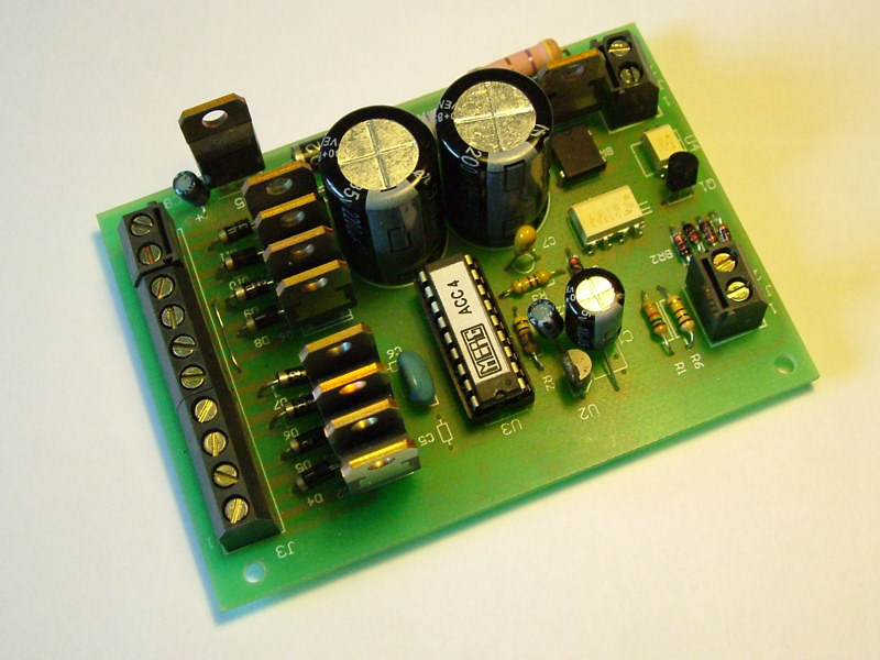
These decoders have a built in Capacitor Discharge Unit (CDU) and are optimised for the operation of solenoid point motors requiring a high current pulse. Each decoder has 4 outputs for twin coil solenoids and each output is capable of operating two point motors as required for crossovers. Full design information including a description of the software can be found on the downloads page.
These decoders require connection to the DCC bus and also a seperate 15-20 Volt AC power supply. Note that the CDU portion will not charge to an adequate voltage if supplied from the DCC bus.
Accessory Decoders for Tortoises etc. (ACC3) Kit 53
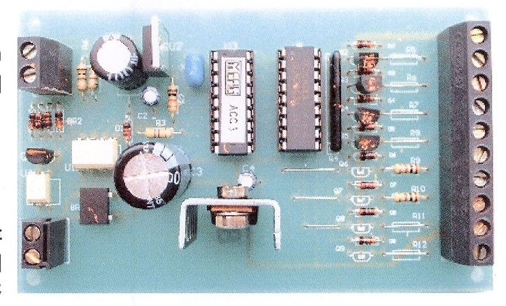
This is a variant of the above decoder with an appropriate output for slow action motors, LEDs etc. It uses the same software. By setting the appropriate Configuration Variables (CVs) the outputs can be continuous or of timed duration. The outputs can be configured as 4 pairs as required for tortoise motors etc or alternatively as 8 independent outputs for using to light signal lamps etc. Full design information including a description of the software can be found on the downloads page.
8-Channel DCC Track Circuit/Block Occupancy Detector (DTC8) Kit 56A
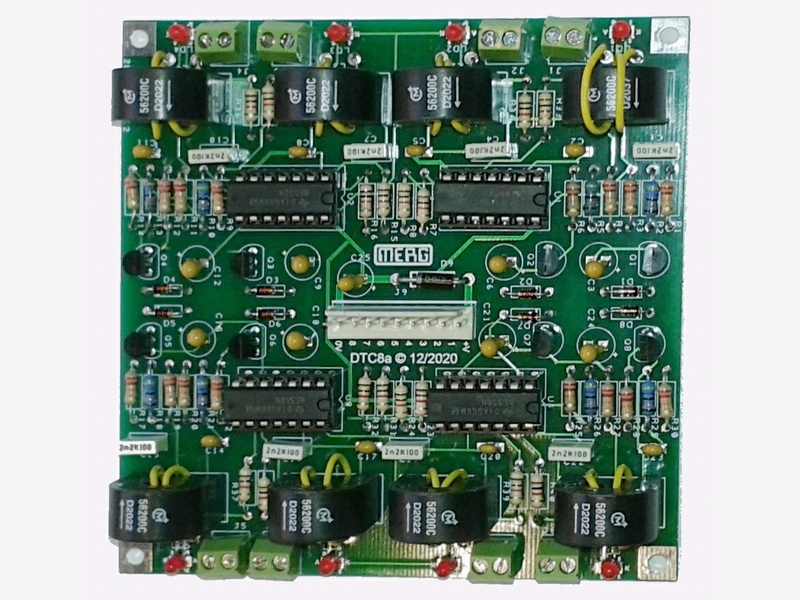
This design detects the current flow through the track to give an indication of the section occupancy. The current may be for a locomotive, a lighted coach or any other rail vehicle with conductive axles. The detector uses a current transformer design to minimise volage drop in the detection circuit and to keep the traction and train detection circuits electrically separate. When the train goes out of section the output from the sensor disappears after a short delay which is prototypical and avoids 'bobbing' indications.
Capable of operation from a power source of 5 - 15v dc, it can drive a panel LED or small relay directly as well as an electronic interface to other Layout Control systems such as the MERG CBUS. The board is designed for detection of 8 sections.
2-Channel DCC Track Circuit/Block Occupancy Detector (DTC2) Kit 50
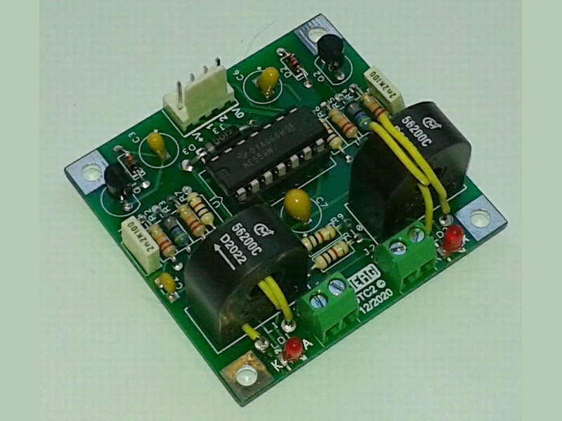
This is 2 channel variant of the DTC using the same detection circuit. It provides a more economical solution where 8 channels are not needed.
Copyright
Copyright for items on this website is retained by the authors. Further licensing details are available on our copyright page.
The use or misuse for the sale, design, supply, process, installation, delivery, test, repair, servicing, and alteration of the designs, instructions, computer code, photographs, circuits, and any other information that appear on this web site is entirely at the risk of the user or visitor to the web site. The information is made available in good faith without warranty of any kind strictly on the basis that no liability will attach to the Model Electronic Railway Group (MERG), its officers and members.