Model Electronic Railway Group
The Leading Society for Model Railway Electronics
More about CBUS® - A Layout Control Bus from MERG
Last updated 4/03/2024.CBUS® - A universal layout control system
note: CBUS is a trade mark registered to Dr Mike Bolton.
CBUS is the product of over 4 years development by MERG members Gil Fuchs and Mike Bolton. During that 4 years CBUS went through many stages of evolution and refinement including some major changes in direction but was sufficiently developed by 2007 to formally introduce the scheme, not just for MERG members but the world at large.
The intention was to develop a system for comprehensive layout control based on a general purpose Layout Control Bus (LCB). The fundamental tenet was that of simplicity, without sacrificing universality, a difficult juggling trick. It had to be affordable and easy to install and set up by non-technical users. It also had to cover the range from small, simple home layouts to the largest and most complex club layout imaginable. Experience has shown this to be achieved. In the years since 2007 many layouts including some very large ones have had CBUS installed and thousands of CBUS kits have been sold. The system continues to grow with many MERG members taking part in the development.
So what are the functions of a layout control system. You can divide these into two basic categories.
- (1)-Control of accessories or devices (outputs)
- (2)-Detection of states (inputs)
Examples of (1) are control panel indications, changing turnouts (points), signals, power to block sections, turntables, level crossing gates, layout lighting, setting routes, controlling the speed and direction of locomotives (by DCC or analogue DC) and any other electrical or electro-mechanical devices that may be on a layout.
Examples of (2) are control panel switches, block occupancy detectors, bar code or RFID readers, turnout direction sensors, turntable position and track occupancy detectors (including Railcom™).
At the basic level, the system can both look and operate like a conventional hard wired system having a control panel with switches to operate turnouts and simple route setting. It also allows use as a 'CAB bus' for DCC systems so handsets (CABs) can be connected to a DCC command station using the same wiring. At the other extreme, it allows full computer control, using multiple computers if necessary, and a fully automated layout with many thousands of inputs and outputs.
The CBUS system can be considered in two parts.
- The hardware
- The messages
Note that the two are not completely independent as the style and frequency of the messages is determined by the hardware capability.
Hardware requirements of the BUS
The choice of CAN.
The CAN bus (Controller Area Network) was developed by the Robert Bosch company in the 1980s for use in motor vehicles but has since been applied to many other types of machinery including aircraft and medical scanners to name just two. It became an open international standard as ISO 11519 in 1994 and a higher speed version as ISO 11898 in 2003. It is now used in virtually all modern motor vehicles so there is a wide applications base and ‘off the shelf’ components are readily available. When we looked at CAN, it seemed pretty much the ideal for an LCB. It was intended for relatively infrequent transmission of small amounts of data between devices for control purposes where response times and safety were paramount. Unlike the more familiar 'Ethernet', it was not intended for shipping large amounts of data between computers. Another advantage of CAN was that it was already in use for an LCB by Zimo, so there was proof it worked in a model railway environment.
The data rate chosen for CBUS is 125Kbps. This is one of the defined CAN rates which go up to 1 Mbps but there is a trade off against cable length. 125Kbps allows lengths of up to 500 metres, good enough for even most garden layouts. The wire should be a twisted pair but doesn't need to be screened. Only the 'standard' CAN frame is used.
The messaging scheme.
After much debate, we settled on the ‘producer-consumer’ model at least for layout control. For those used to the idea of sending specific messages from A to B – a ‘source-destination’ scheme, this is a very different concept although widely used for industrial control systems. Imagine changing a switch on a control panel. This creates an ‘event’. A frame is sent on to the bus which contains no destination address, no information, just an ‘event’ number. The node sending an event is called a ‘producer’. All nodes capable of processing an event are ‘consumers’. Every consumer on the layout receives the event. What the consumer does with the event will depend on information already in the consumer. In effect, a consumer has to be taught what to do with any event it has to act on and will ignore events that are not relevant.
This is an extremely powerful and very flexible arrangement. Producers can send many events. Many consumers can act on an event and in different ways. Consumers can also act in the same way for different events. Note that hardware modules may act as producers for some events and consumers for other events, or even for the same events. There is immense flexibility.
The above description may seem rather abstract. I will use a recognisable example. You want a push button (PB) on a control panel to set a route and the corresponding signals. You have a producer node on the control panel. You have a number of consumer nodes that drive turnouts and signals. Let's say the PB creates event number 1. Turnout controller A has been taught that event 1 means set turnout 1 to normal, turnout 2 to reverse. Turnout controller B has been taught that event 1 means set turnout 3 to reverse, turnout 4 to reverse and turnout 5 to normal. Signal drivers C and D have been taught that event 1 means set the various signals or aspects for that route. Pressing the one PB sets the route and all the signals in one go. Obviously, a different PB could send event 2. The various consumers would know to act on event 2 in a different way to event 1 so set a different route.
With this P-C model, you have effectively transferred some of the decision making from the producer to the consumer. It still allows for computer control or assistance such as interlocking, if the PC or other interlocking system is placed between the original producer and the final consumer. Now, the switch event is recognised by the PC (as a consumer) and when a decision has been made, the PC sends another event (as a producer) to the final layout consumers. Items like block occupancy detectors, connected to module inputs, are producers of events so a PC can know if a block is occupied.
While full PC operation is easily accomplished, it is equally easy to configure quite complex layouts without any ‘programming’ at all. The latter will be described in our Small Layout implementation Model (SLiM).
Scope of CBUS for layout control
A CBUS message consists of a ‘command’ byte and an ‘event number’. The command byte is used to set the number of bytes in the message and define the type of event. For layout control we only use at present an ‘ON’ event and an ‘OFF’ event but for CAB bus implementation, a number of other ‘commands’ are also used. As nodes need to know how to respond to an event, there needs to be a mechanism for teaching them. Each programmable node is given a node number (NN) of 16 bits or two bytes. If nodes are to be unique, the maximum number of nodes is 65536 or 64K. Each producer node is allowed a further 16 bit range for its events giving a possible 4.29 billion events! The actual event number in a message is comprised of the node number and the node event so the final event is a 32 bit number. This allows events to be traced to a particular node as well as preventing accidental duplication of events from different nodes.
Sometimes it is desirable to allow events to be produced by more than one producer, eg if duplicate control panels are needed, for this purpose alternative command bytes are used that instruct the consumer to disregard the node number bytes and act on the 16 bit event number.
Providing a consumer is a ‘receive only’ device, there is no limit to the number of these. In our SLiM model, such consumers are taught using on-board switches so a node number is not required.
However, there are other limits for the number of nodes set by the CAN bus requirements. Each node requires a CAN transceiver IC which drives the bus with the CAN information. Currently available transceivers set a limit to the number of nodes on a bus ‘segment’ to 110.
One of the features of CBUS is the complete separation of the message from the ‘transport’. Where more than 110 nodes are wanted, we can use repeaters that link different CAN segments. All that is sent between segments is the message (command and event) so each segment may have duplicate CAN frame arbitration headers. Given enough repeaters (CAN-CANs), the node limit is set at 65536 by the CBUS protocol.
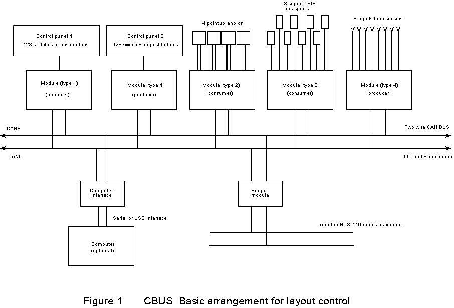
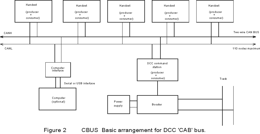
Figure 1 shows a simplified arrangement for a layout control scheme and figure 2 shows a CAB bus arrangement. The actual bus wiring is common to both, only the one bus is rerquired to cover both functions.
CBUS implementation - DCC
The DCC specific CBUS modules, the DCC Command Station (CANCMD) and Hand Controller (CANCAB) allow DCC operation to be fuly integrated in the CBUS environment, more details of these DCC modules are available on a dedicated DCC page. The DCC modules can be used as a stand alone DCC system or fully integrated with other CBUS modules using either the SLiM or FLiM models discussed below.
CBUS implementation – the SLiM model.
The thinking behind the SLiM (Small Layout implementation Model) is for a collection of modules for layout control that need no programming and no programming device. A layout can be configured using just switches on the modules. This was originally implemented for the following modules: CANACE8C (8 inputs), CANACC8 (8 simple outputs), CANACC4 (outputs for 4 solenoid point morots), CANACC5 (outputs for 4 bi-polar motors), CANACE3C (inputs for up to 128 panel switches), and CANLED64 (outputs for up to 64 panel LEDs).Experience has shown that users of the more complex modules such as those for panels quckly moved to the FLiM model using a PC for configuration so our current range of kits for the SLiM model are those listed in the 'basic' range on the main CBUS page. These are the CANINP, CANOUT and CANSOL. For the small layouts commonly use with the SLiM model panel switches and LEDs can be covered by the CANINP and CANOUT.
CANINP, an 8 input switch/ogic level detector, this node can generate an event corresponding to its input states in response to a ‘request’ event (which will be useful for interlocking and reading logic levels or switch positions).
CANOUT, an 8 output relay/lamp/logic driver with adjustable voltage.
CANSOL, A solenoid turnout driver with 4 output pairs and a CDU
CBUS implementation – the SLiM model continued.
The novel aspect of the CBUS SLiM model is the way the nodes are ‘taught’ how to respond to an event.
The producers are provided with DIL switches which set their Node Number. The switch input node has a 4 way switch allowing 16 such nodes, each with 8 inputs. Note, these are only hardware design constraints and not intrinsic to CBUS. The only requirement for these producer nodes is that no two may have the same number. The actual number is irrelevant. These producer nodes create events numbered according to their inputs as the lower two bytes. The upper two bytes of the 32 bit event are the node number.
The SLiM consumers do not have a node number. They have a DIL switch to select an output, a ‘learn’ switch, an ‘unlearn’ switch and a ‘polarity ‘switch. To link an output with an input event, the following sequence is followed. The nodes are connected to the bus and powered up. One (or more) consumer nodes are put into ‘learn’ mode with their switches and the output to be associated with an event is selected on each with the DIL switches. For the solenoid turnout drivers, there are 4 outputs, for the relay / LED driver there are 8 outputs. The input on a producer is activated (say a control panel pushbutton) and it sends an event. The consumers remember this event and activate their outputs. You can check if the action is what you wanted. The action can be repeated as many times as you like. If satisfied, you take the consumers out of learn mode. All subsequent events with that event number will cause the same output actions.
Each event can be either ON or OFF while still having the same event number. This allows an input ON/OFF switch to be regarded as a single event producer. The purpose of the ‘polarity’ switch on the consumer nodes is to allow an output to work in reverse relative to the event. If this switch is set while learning, the output action is reversed.
Apart from its use in setting routes, where some outputs need to be set and some cleared with the same event, it also allows different outputs on the same consumer to act in opposite directions. Thus two outputs can be ‘toggled’ with one event. Also, if using the 8 output driver, you can set multiple aspect signals to have a different aspect for each event – 256 possible combinations.
The possible permutations and combinations, even with this very simple scheme, are endless, ranging from a single control panel switch operating a single turnout to pushbuttons on different control panels setting the same complex route. If the turnouts are equipped with sensors (microswitches etc), these can be fed to a producer such as the 8 input node to create events to confirm turnout operation. In turn these events may switch lights on a control panel via a LED driver module. A block occupancy detector with a logic level or ‘open collector’ output can create events via an input producer module. Here it would create an ON event when the block became occupied and an OFF event when cleared.
The SLiM scheme does not need any programming device. The user doesn’t need to know any node or event numbers. The only requirement is that no two producer nodes should have the same node number. The SLiM scheme presently limits the number of producer nodes, (CANINPs) to 16. There can be any number of consumer nodes in principle but the CAN bus transceivers will only allow 110 nodes total on a single segment.
CBUS implementation – the FLiM model.
While the above describes our SLiM (Small Layout Model) of CBUS, the principle has been expanded to the ‘Full’ model (FLiM) where all nodes / modules are fully programmable over the same CBUS. This is intended for larger layouts and allows a maximum of 65535 individual nodes. As the message structure and format is the same for both SLiM and FLiM, there is an easy upgrade path from SLiM to FLiM and both types of module will work together.
A Configuration utility (FCU) running on Windows PCs is available to allow simple configuring of a CBUS system in FLiM mode. This is so straightforward that all but the smallest CBUS systems now use FLiM mode and an increasing number of modules are being designed with features that cannot be used in the SLiM mode. Kits for hese are shown as 'Advanced' and 'Explorer' on the main CBUS page. Use of FLiM allows for substantially enhanced functionality. In addition to the MERG kits there are many designs produced and published by members with bespoke functionality that can be built and used with the system.
CBUS - More information
CBUS is a registered trademark of Dr Mike Bolton Registration No. UK00003503053 The controlled version of the Developers' Guide is available at cbus-traincontrol.com
Mike Bolton and Gil Fuchs, from November 2007, last update March 2024, Keith Norgrove.
Copyright
Copyright for items on this website is retained by the authors. Further licensing details are available on our copyright page.
The use or misuse for the sale, design, supply, process, installation, delivery, test, repair, servicing, and alteration of the designs, instructions, computer code, photographs, circuits, and any other information that appear on this web site is entirely at the risk of the user or visitor to the web site. The information is made available in good faith without warranty of any kind strictly on the basis that no liability will attach to the Model Electronic Railway Group (MERG), its officers and members.